So, what is a Screw Gauge? A screw gauge, also known as a micrometre screw gauge, is a measuring instrument used to determine the accurate measurements of small objects. For example, consider the thickness of glass and the diameter of a thin wire or a tiny spherical.
The first screw gauge was developed and used in a telescope to measure the angular distances between stars and other celestial bodies. The Pitch scale and the Circular scales are used to measure the readings.

Parts of the Screw Gauge
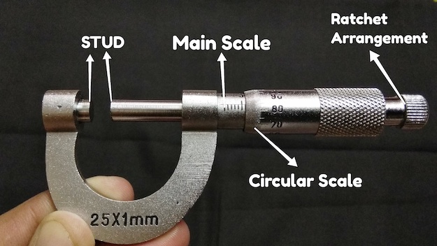
The following are various components of a Screw Gauge:
1. Frame: Screw Gauge is made up of a U-shaped metallic frame.
2. Anvil: Anvil, a fixed stud with a plain face, is fastened to one side of the U frame. This is the smallest of the two studs.
3. Spindle: A long hollow cylindrical tube with a long stud with a plane face is inserted into a nut on the other side of the U frame. A consistent thread is cut into the inner surface of the cylindrical nut. Spidle and Anvil’s faces are flat and parallel to one another.
4. Barrel or Sleeve: The barrel, also known as a sleeve, links the frame to the cylindrical tube. It is a non-movable portion of the screw gauge with a scale etched on it and serves as the device’s main scale. Furthermore, it transports the micrometre’s most critical component—the screw.
5. Thimble: The thimble, or head, is the cylindrical tube’s end that is turned to move and adjust the spindle. The thimble carries the vernier or secondary scale.
6. Ratchet: The ratchet is a limiting mechanism that delivers pressure by sliding at a specified torque, preventing the spindle from going any further.
7. Screw: The screw positioned inside the barrel is the micrometre’s heart. Using a scale, the screw translates minuscule dimensions into the quantifiable distance.
8. Lock: Some screw gauges also have locking mechanisms that keep the scales in a specific position to prevent errors while collecting readings.
9. Scales: A screw gauge features two scales: one spinning scale on its rotating cylindrical component, a circular scale, and the other on its stationary sleeve, the main scale or sleeve scale. On the main scale, the smallest count is o.5 millimetres. The circular scale is divided into 50 or 100 equally spaced sections.
Working Principle of a Screw Gauge
# A screw gauge functions in the same way as a screw in a nut does.
# It measures the screw’s rotation, converting short lengths into long distances.
# Two factors determine its operation: pitch and least count.
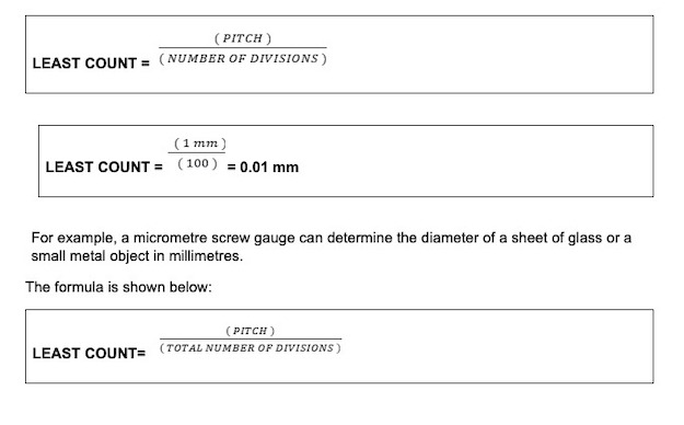
# Pitch is defined as the spacing between two subsequent threads. The pitch is also described as the distance travelled divided by the number of rotations. The least count is the ratio of pitch and the total number of divisions on the circular scale.
# The measurements are taken using a perfectly machined integrated screw with a pitch of typically 2 threads per millimetre, implying that the displacement attained after one round is 0.5 mm.
Formula of Using a Screw Gauge
Screw gauge calculates the result using two formulae. The screw gauge’s pitch or the least count of screw gauge is employed. The third formula, which calculates the least count of the micrometre, has limited applicability.
Pitch of the screw gauge – Pitch is the ratio between the distance a screw travels and the number of rotations the screw makes.
The formula is given below:

Least count of the screw gauge – This is calculated by dividing the pitch by the number of divisions.
The formula is as follows:


PSR is Pitch Scale Reading
CSR is Circular Scale Reading
LC is the Least Count
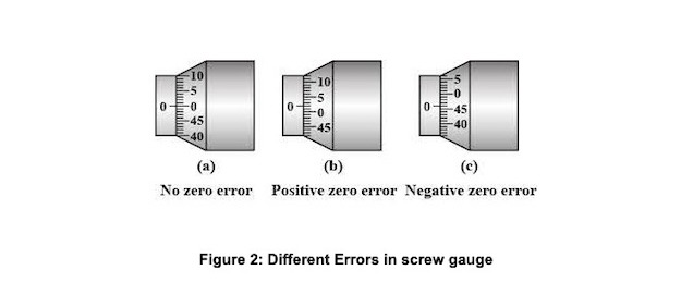
Sometimes the zero of the pitch scale does not coincide with the zero of the circular scale. According to Figure 2, a scale can be above or below the pitch scale( the main scale).
Errors In Screw Gauge

(A) Zero Error: There is no error if the zeros in the circular scale and main scale exactly overlap at the stud and spindle ends of the screw.
(B) Positive Error: A positive error occurs when the zero of the circular scale lies below the reference line or index line. The zero correction will therefore be positive.
(C) Negative Error: The error is negative if the zero of the circular scale is above the index line (reference) line. Therefore, zero correction will be positive.
Now the formula becomes:

Here is an example of how to use a Screw gauge
Example 1
Let us calculate the diameter of the wire:
1. Tighten the provided wire between the stud and spindle by rotating the ratchet clockwise.
2. Note down the main scale reading (M.S.R.) (that is visible one on the horizontal line just beyond the circular scale.
3. Notice how the circular scale division indicates ‘n’ right before the index or reference line.
4. Here you need to multiply ‘n’ by the least count (L.C) to get a fraction of the circular scale reading, which is then multiplied by the main scale reading.
5. So the diameter of the wire will be calculated as (M.S.R C.S.R) zero correction.
Conclusion
It is crucial to handle micrometre screw gauges with special care since they are delicate devices. Additionally, a well-calibrated micrometre is also necessary to avoid any error in the final reading.


